White Powder and Blueish Buckets

The temperature hovers just above freezing this morning but with wool socks, my feet are plenty warm within my steel-toed Redwing boots. The mist of Kroil stings my nostrils but that is more pleasant than the olfactory assault of a grinding wheel on steel. I can taste it all on my lips. The rattling of impact wrenches penetrates my earplugs and jars my brain. The bright orange FME covers on the open flanges provide the only contrast to the cold gray metal that surrounds me.

This combustion turbine overhaul is similar to many, but when the fuel nozzles, liners and flow sleeves come out, they are coated with a mysterious white powder.
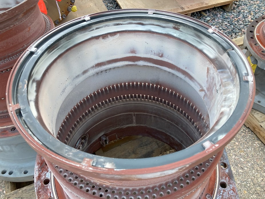
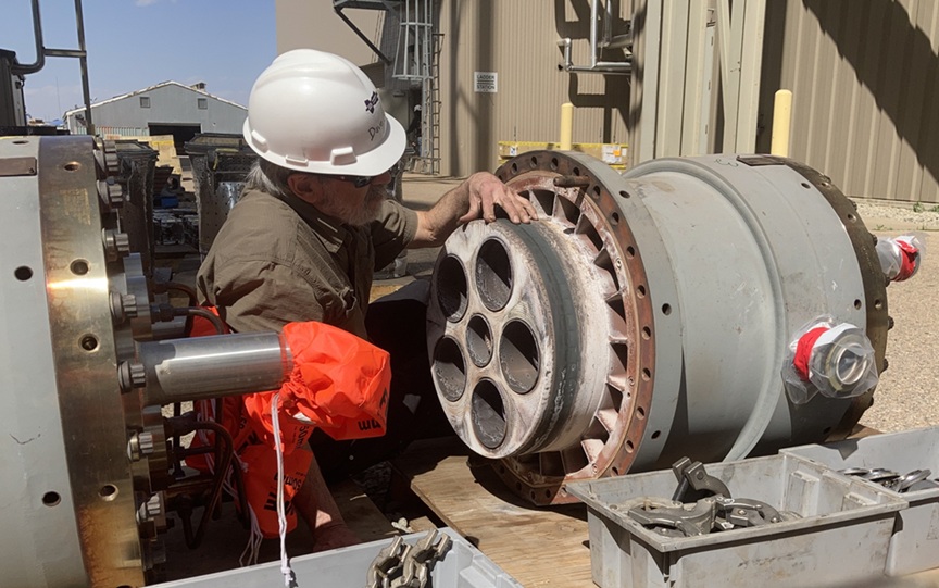
Samples of the white powder were sent to the lab and analysis reveals that this substance is sodium sulfate[1] (Na2SO4), a corrosive salt. Bingo! My memories flash back. When this mineral gets sucked into the flame, it melts and passes through stage 1 only to condense when the temperature drops in the second stage of the turbine. This molten mineral goo can stick to the airfoils. If turbine buckets are not protected by an MCrAlY coating, the “hot corrosion” could quickly eat into the base metal and caused a catastrophic failure. Even so, this hot corrosion will eventually eat through the MCrAlY.

When we get the turbine case off, my eyes are immediately drawn to the blueish tint of the stage 2 buckets, and my mind rewinds to an overhaul two decades ago that exhibited a similar condition. The term “hot corrosion” comes to mind, but let’s not jump to conclusions without some help from the chemistry department and a trusted metallurgist. Their assessment confirms my suspicions.
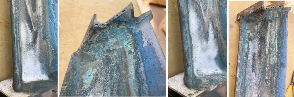
Until they are chemically stripped at the repair shop, we won’t know how compromised these buckets may have been. I suspect they will find patches with deep corrosion grooves on the surface and possibly voids beneath, but as the adage goes:

“One valid test is better than a thousand expert opinions.”

I try to chip off little samples from multiple buckets, but it is very difficult, and I have to be satisfied with a half teaspoon after much effort. The uneven splattering of these condensed minerals on the airfoils may explain why the turbine efficiency decreased in the last several months of operation.

Although the reductionist in me understands that this is sodium sulfate, I must ask “where did this come from?” My previous experience leads me up a tall ladder and into the inlet filter house. I crawl though the Hobbit door and continue to the downstream side of the evaporative cooler. As suspected, the knees of my black Carhartt jeans are now white, coated with sodium sulfate. The root cause, I believe, is high mineral content in the water used by the evap cooler combined with excessive flow which led to carryover. The high mineral water carried over to form puddles in the trough downstream of the mist eliminator and other low points, and eventually evaporated leaving the minerals behind which got sucked into the compressor and beyond.
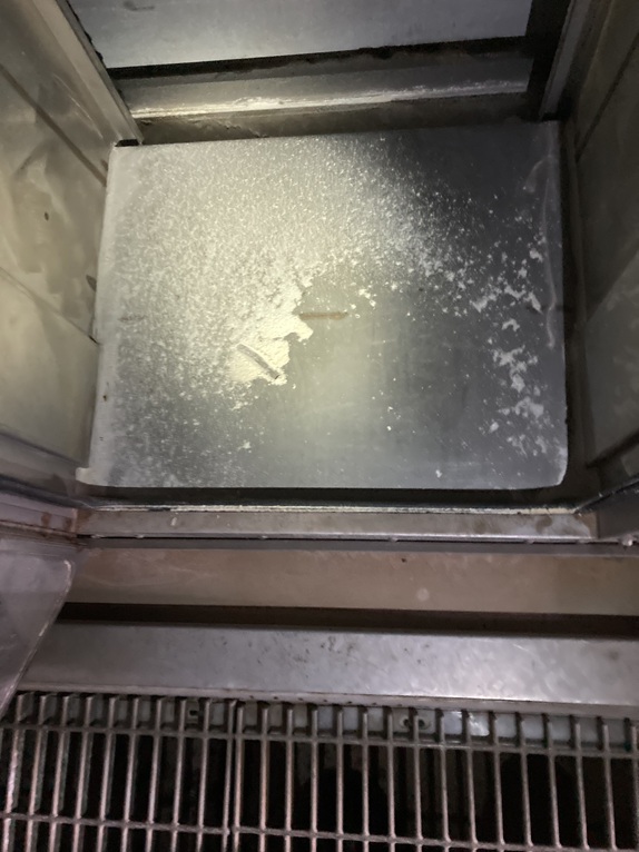
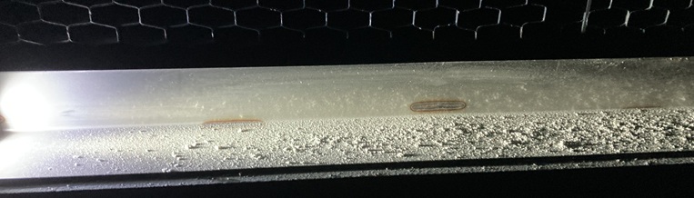
Just to be sure, I sample the powder here and compare it to what was adhered to the combustion components. It is basically the same animal… sodium and sulfur.

At this point, the logical questions are these:

  1. Can we improve the chemistry of the evap cooler water by blowing down the sump when the conductivity reaches a certain level?
  2. Can we improve the chemistry of the evap cooler water by blending domestic or well water with demineralized water?
  3. Can we reduce excess water overflow (carry-over) from the evap media and mist eliminators?

Yes, yes, and yes, but not without effort. The payback will be to preserve turbine efficiency and to reduce refurbishment or fallout replacement costs. If you need suggestions or help with 1) and 2), give me a call. And for 3), again, you can give me a call if you like. I can instruct you and/or help you commission your evap cooler when you return it to service in the spring.

Don’t let water with high mineral content (or the powdered minerals it left behind) enter your compressor, combustion system, and turbine. The potential hot corrosion will cost you in the long run, but it can be minimized.

I am an engineer, not a chemist nor a metallurgist, so if anyone with those credentials would like to add anything (or correct me), please chime in by leaving a comment below. Here is a good reference article describing the hot corrosion phenomenon:

https://www.sciencedirect.com/topics/materials-science/hot-corrosion


[1] Fun fact: The white powder form of Na2SO4 used to be known as Glauber’s salt which was used as a laxative from the mid-1600s up until the invention of Ex-Lax Milk of Magnesia and the like in the early 1900s. But please – don’t try this at your power plant.

Stranger Than Fiction

This is a story I published on my personal blog a few years ago, but it will be fun to repeat it here. But please forgive me if I “over-explain” things for this technical audience.

I am a mechanical engineer who primarily oversees work on GE 7FA combustion turbines that drive generators that produce electricity at power plants. That is my job. These units contain a large axial compressor that feeds combustion and cooling air for the gas turbine section. During a recent inspection on one of the units, we discovered damage within the compressor that required an emergency repair.

The outer case is assembled with over a hundred bolts that are approximately an inch diameter by a foot long. These are removed with the force of a hydraulic wrench and then our crane can remove the upper case which weighs over five tons. The stationary vanes in the forward part of the compressor are mounted into carrier rings that slide into a hook in the case. With significant metal-to-metal contact, rust and corrosion tends to seize these rings in place making them extremely difficult to remove. In this case, the damage is down at the bottom (six o’clock position) and we need to remove the lower rings.

If that description does not give you a mental picture, here are a couple visuals….

Open CompressorGE 7FA axial compressor with upper case removedCarrier Ring with VanesCarrier ring with stator vanes after being removed from lower half hook fit

Chemists from around the world have developed various solvents that dissolve certain types of corrosion without attacking the base metal. Some of these solvents are brushed on, some are sprayed on, some are poured into a tank and have parts dipped into them or set in overnight to soak like dishes in a kitchen sink. On this compressor, there is a narrow gap between the carrier ring and the case, and typically, various solvents or penetrating oils are poured down this gap to loosen and dissolve ring-to-case rust and corrosion. This step is necessary if there is any hope of removing these carrier rings.

I don’t want to give away too many trade secrets, but there is a solvent that is much cheaper and perhaps more effective than others. This product is also pretty useful for cleaning toilets, among other things. And… it’s the real thing.

Coca ColaCoca-Cola – “It’s the real thing”

A fact that continues to amaze me is that some people are known to voluntarily pour this powerful solvent into their mouths and down their own throat. You can’t make this stuff up. As they say, sometimes truth is stranger than fiction.

Stage 1 Nozzle Refurbishment

On many combustion turbines, certainly on the GE 7FA, the Stage 1 Turbine Nozzle is probably the most critical component for turbine performance and emissions margin. The throat area plays a big factor in the amount of hot gas flowing through the turbine, and it also plays into the compressor pressure ratio (CPR) which affects firing temperature. This component also has the potential of using too much of the precious compressor discharge air whether by excessive cooling air consumption, or bypassing this air around the chordal hinge seal.

who cares if it is round? I do.

A perfectly round nozzle ring is not necessary, but if it is out of round / elliptical by more than 1/8 inch, not only will it make transition piece installation more difficult, but it is a sign that something is wrong. It could be that the support ring itself is warped, but that is what usually gets all the attention and is not typically the problem. The horizontal joint seals may not be fully engaged, but that can be remedied. The main problem is if the duplex airfoil segments get warped (too much heat during weld repairs) and subsequently jammed into the support ring. This will warp the overall ring and could cause gaps in the chordal hinge which is supposed to seal axially against the stage 1 shroud blocks. A good after-the-fact check for this is to look at the downstream side of the used nozzle ring during an outage after a run and look for rusty-colored streaks. Those are tell-tales of a leaky chordal hinge.

throat area

Through a long series of precise measurements, the “throat” between the forty-eight stage 1 nozzle airfoils is calculated. The turbine is designed for a specific throat area. If it is too large, it will cause one type of problem, and if too small, it will cause another type of problem, both of which will affect overall turbine efficiency and MW output. There is an optimal range for S1N throat area, and your refurbishment vendor should know this target and report how close they got. If this is not a part of your repair spec, we can help.

all those little cooling holes

The stage 1 nozzle airfoil segments are cooled by compressor discharge air through ports in the outer support ring. The air passes through perforated inserts and out through small cooling holes strategically located in the airfoils and platforms. There are two circuits, one to the leading edge and one to the trailing edge. GE issued a Technical Information Letter (TIL) which describes performance issues (high NOx / low output) after installing refurbished stage 1 nozzles, and they point to excessive cooling air flow. Some vendors take this very seriously while others prefer to ignore it because it is complicated to measure and expensive to remedy. If your repair vendor does not look at this, you need to find someone who does.

What is That Sound?

Audible Combustion dynamics

You have probably been out at the unit during a startup and heard the low-frequency rumble when the combustion system lights off. It might remind you of a passing freight train. But what about during normal operation, maybe even at base load? If you hear a similar sound then, it may be a sign of trouble.

What to do?

The low-frequency (~16 Hz) chug, or “lean-blow-out” (actually a misnomer) combustion dynamics is audible if it approaches 1 psi peak-to-peak amplitude. This resonance often occurs when the DLN 2.6 outer fuel nozzles (PM2 and PM3) are flowing very similar amounts of fuel gas. This is sometimes called “even splits” and is the PM3 split value that produces the lowest NOx. However, once these tones are excited, they can easily get amplified and at some point (when the walls of the PEECC begin to shake), the sound will literally blow out your flame, even at base load.

With a typical PM3 split schedule, reducing load will usually back you away from this problem, but if you are sitting at the controls and have access to the PM split schedule, ramp up the PM3 splits +1% or 2% as fast as possible. If you have a good autotune program, this is what should happen automatically. This will break up the uniformity of the outside diameter of the flame and defuse that resonant 16 Hz acoustic dynamics. You might then be stuck with NOx that is higher than you like, but that is a different story and a job for a tuner.